- 您现在的位置:买卖IC网 > Sheet目录2007 > MAX11046ECB+T (Maxim Integrated Products)IC ADC 16BIT PAR 250KSPS 64TQFP
4-/6-/8-Channel, 16-/14-Bit,
Simultaneous-Sampling ADCs
11
Maxim Integrated
MAX11044/MAX11044B/MAX11045/MAX11045B/
MAX11046/MAX11046B/MAX11054/MAX11055/MAX11056
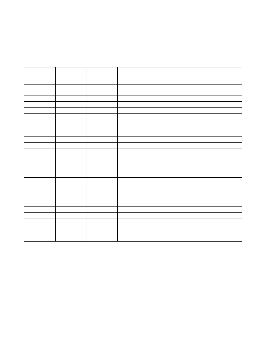
Pin Description (continued)
MAX11044/
MAX11044B
(TQFN-EP)
MAX11045/
MAX11045B
(TQFN-EP)
MAX11046/
MAX11046B
(TQFN-EP)
NAME
FUNCTION
24, 30, 41, 47
AVDD
Analog Supply Input. Bypass AVDD to AGND with a
0.1μF capacitor at each AVDD input.
25, 31, 40, 46
AGND
Analog Ground. Connect all AGND inputs together.
32
29
26
CH0
Channel 0 Analog Input
34
32
29
CH1
Channel 1 Analog Input
37
34
32
CH2
Channel 2 Analog Input
39
37
34
CH3
Channel 3 Analog Input
36
REFIO
External Reference Input/Internal Reference Output.
Place a 0.1μF capacitor from REFIO to AGND.
—
39
37
CH4
Channel 4 Analog Input
—
42
39
CH5
Channel 5 Analog Input
—
42
CH6
Channel 6 Analog Input
—
45
CH7
Channel 7 Analog Input
52
WR
Active-Low Write Input. Drive WR low to write to the
ADC. Configuration registers are loaded on the rising
edge of WR.
53
54
CS
Active-Low Chip-Select Input. Drive CS low when
reading from or writing to the ADC.
54
RD
Active-Low Read Input. Drive RD low to read from the
ADC. Each rising edge of RD advances the channel
output on the data bus.
55
DB15
16-Bit Parallel Data Bus Digital Output Bit 15
56
DB14
16-Bit Parallel Data Bus Digital Output Bit 14
26, 29, 42, 45
26, 45
—
I.C.
Internally Connected. Connect to AGND.
——
—
EP
Exposed Pad. Internally connected to AGND. Connect to
a large ground plane to maximize thermal performance.
Not intended as an electrical connection point.
发布紧急采购,3分钟左右您将得到回复。
相关PDF资料
MAX11046ETN+T
ADC 16BIT SAMPLING 8CH 56-TQFN
MAX11049ECB+
IC ADC 16BIT PAR 250KSPS 64TQFP
MAX1104EUA+
IC CODEC 8BIT 8-UMAX
MAX11100EUB+
IC ADC 16BIT SRL 200KSPS 10UMAX
MAX11101EUB+
IC ADC 14BIT SRL 200KSPS 10UMAX
MAX11102AUB+
IC ADC 12BIT SPI/SRL 10UMAX-EP
MAX1111CPE+
IC ADC 8BIT LP 16-DIP
MAX1113CPE+
IC ADC 8BIT LP 16-DIP
相关代理商/技术参数
MAX11046ECB+TW
功能描述:模数转换器 - ADC 16-Bit Simultaneous Sampling ADC RoHS:否 制造商:Texas Instruments 通道数量:2 结构:Sigma-Delta 转换速率:125 SPs to 8 KSPs 分辨率:24 bit 输入类型:Differential 信噪比:107 dB 接口类型:SPI 工作电源电压:1.7 V to 3.6 V, 2.7 V to 5.25 V 最大工作温度:+ 85 C 安装风格:SMD/SMT 封装 / 箱体:VQFN-32
MAX11046ECB+W
功能描述:模数转换器 - ADC 16-Bit Simultaneous Sampling ADC RoHS:否 制造商:Texas Instruments 通道数量:2 结构:Sigma-Delta 转换速率:125 SPs to 8 KSPs 分辨率:24 bit 输入类型:Differential 信噪比:107 dB 接口类型:SPI 工作电源电压:1.7 V to 3.6 V, 2.7 V to 5.25 V 最大工作温度:+ 85 C 安装风格:SMD/SMT 封装 / 箱体:VQFN-32
MAX11046ETN+
功能描述:模数转换器 - ADC 16Bit 8Ch Simult Sampling
RoHS:否 制造商:Texas Instruments 通道数量:2 结构:Sigma-Delta 转换速率:125 SPs to 8 KSPs 分辨率:24 bit 输入类型:Differential 信噪比:107 dB 接口类型:SPI 工作电源电压:1.7 V to 3.6 V, 2.7 V to 5.25 V 最大工作温度:+ 85 C 安装风格:SMD/SMT 封装 / 箱体:VQFN-32
MAX11046ETN+
制造商:Maxim Integrated Products 功能描述:IC ADC 16BIT 250KSPS TQFN-56
MAX11046ETN+T
功能描述:模数转换器 - ADC 16Bit 8Ch Simult Sampling RoHS:否 制造商:Texas Instruments 通道数量:2 结构:Sigma-Delta 转换速率:125 SPs to 8 KSPs 分辨率:24 bit 输入类型:Differential 信噪比:107 dB 接口类型:SPI 工作电源电压:1.7 V to 3.6 V, 2.7 V to 5.25 V 最大工作温度:+ 85 C 安装风格:SMD/SMT 封装 / 箱体:VQFN-32
MAX11046ETN+TW
功能描述:模数转换器 - ADC 16-Bit Simultaneous Sampling ADC RoHS:否 制造商:Texas Instruments 通道数量:2 结构:Sigma-Delta 转换速率:125 SPs to 8 KSPs 分辨率:24 bit 输入类型:Differential 信噪比:107 dB 接口类型:SPI 工作电源电压:1.7 V to 3.6 V, 2.7 V to 5.25 V 最大工作温度:+ 85 C 安装风格:SMD/SMT 封装 / 箱体:VQFN-32
MAX11046ETN+W
功能描述:模数转换器 - ADC 16-Bit Simultaneous Sampling ADC RoHS:否 制造商:Texas Instruments 通道数量:2 结构:Sigma-Delta 转换速率:125 SPs to 8 KSPs 分辨率:24 bit 输入类型:Differential 信噪比:107 dB 接口类型:SPI 工作电源电压:1.7 V to 3.6 V, 2.7 V to 5.25 V 最大工作温度:+ 85 C 安装风格:SMD/SMT 封装 / 箱体:VQFN-32
MAX11046EVKIT+
功能描述:数据转换 IC 开发工具 MAX11046 Eval Kit
RoHS:否 制造商:Texas Instruments 产品:Demonstration Kits 类型:ADC 工具用于评估:ADS130E08 接口类型:SPI 工作电源电压:- 6 V to + 6 V